Table of Contents
Our friend, who owns a CMM1200 mower, was unable to run her mower because of a broken hinge pin on the orange switch lever. This is the pin that allows the switch lever to pivot and turn the mower on:
Important note: if you have a question to ask, please ask it at Lawn Mower Forum, either in the Black & Decker area or the Electric & Battery Operated area at that website. I apologize for being unable to handle individual requests for help posted on this blog or sent by email.
From the Black & Decker CMM1200 Instruction Manual.
Before I detail how to fix this, let me just say this appears to be a common problem on the CMM1200, judging from owners' comments at both Amazon and eReplacementParts. It also looks like Black and Decker later redesigned the mower so that, in the Type 2 version, the pin is a $1 replacement part instead of a part of the larger, more expensive switch clamshell. So owners of CMM1200 Type 2 mowers may want to simply order the pin replacement here.
To fix my friend's mower (a Type 0 version, which I didn't even know existed until now), it was necessary to come up with some makeshift hinge pin, and drill a hole in the outer clamshell to accommodate it. If possible, I wanted it to:
- Be made of metal, or include metal, so that it would not break again, and
- Not have exposed screw threads that would rub against (and possibly damage) the orange switch handle.
- A 1-1/2" long, 4-40 screw, (preferably stainless steel or brass, or other non-rusting material)
- A 1" long, 3/16" diameter nylon spacer
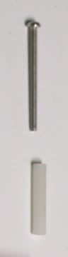
Screw and spacer
Tools I used for this job include:
- A power drill
- A screwdriver for size T25 Torx head screw
- Drill bit for 4-40 tap - ideally size #43, but 5/64" worked for me.
- A 4-40 tap and tap wrench
- A hole punch
- A hand file
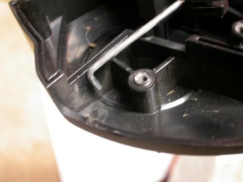
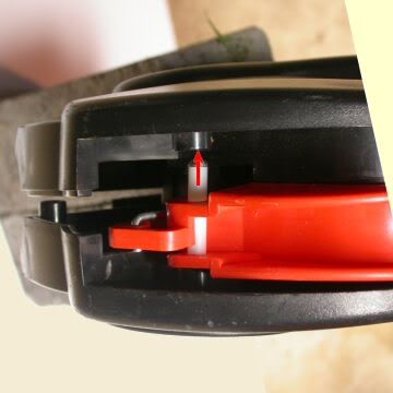
Drilled-out portion of lower clamshell. This is where the original plastic pin was located before it broke off.

Close up view.
I won't offer instructions on how to tap a threaded hole -- it's really better to be shown in person how to do this, as it is just too easy to do it wrong and strip the threads. If you don't have the means to tap threads yourself, consider drilling a 1/4" deep hole that you can slip the 4-40 screw into; a 1/8" drill would work for this.
The screw head was too big to fit into the socket of the upper clam shell, but not by too much. I inserted the screw in my power drill, turned on the drill, and rubbed the screw head against a hand file until it finally fit in the socket. The locked-on feature of my drill made this easy, as it freed up a hand that would otherwise have to hold the trigger in the on position.
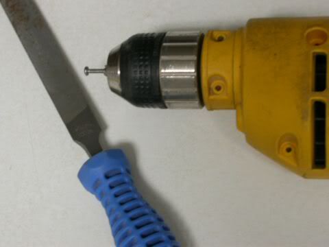
Insert the screw far enough so that the end threads are not damaged by the drill chuck.
Next, I hand-tightened the screw and spacer into the threads in the lower clam shell. It would be easy to strip the plastic threads by overtightening with a screwdriver, since it is a metal screw and the threads are rather small. (Ideally I would have preferred larger 6-32 threads, but I couldn't think how to incorporate that screw size in an easy, satisfactory way.)
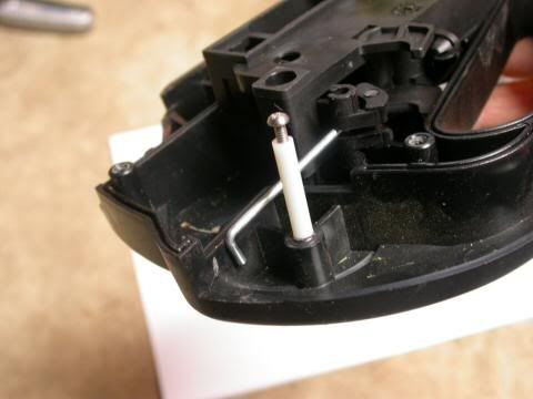
The lower plastic clam shell (which used to include the now-broken-off plastic pin) and new hinge pin.
For the final steps:
- the spring and switch lever are slipped over the makeshift pin
- the heavy wire switch link is fitted into the hole in the switch lever
- the two outer clam shells are screwed together
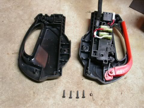
Upper clam shell at left; lower clam shell with orange lever at right. At this point of the assembly process, I had no idea what the spring (to right of 4 screws) was for. Nor did I include it when taking this photo; what you see here is a sketch of the spring that I have photoshopped into the picture. In fact the spring should already be in the assembly here, not laying aside with the still-to-be-used parts.
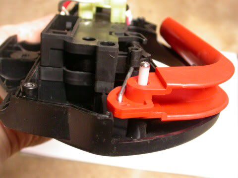
Lower clamshell, with orange lever and new hinge pin.
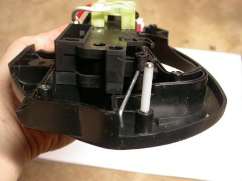
Upper & lower clamshells, showing socket that accepts the screw head.
(Pssst! Don't forget the spring -- missing here, see next pic).
(Pssst! Don't forget the spring -- missing here, see next pic).
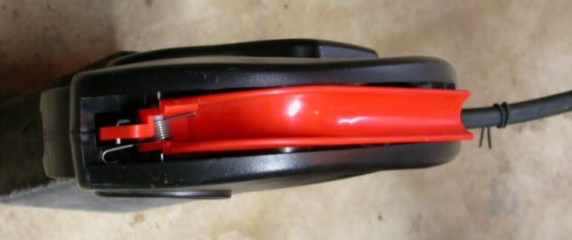
The switch assembly is finally together, including the spring.
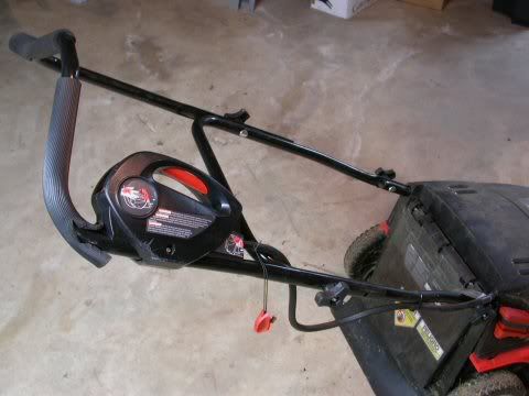
After testing that the mower will start, you are ready
to reattach the switch assembly to the mower handle.
to reattach the switch assembly to the mower handle.
There are any number of ways to fashion your own hinge pin.While 3/16" is a suitable and easy-to-find part diameter, it really just needs to be able to fit though both the 0.227" holes in the orange handle as well as the 0.205" hole in the upper clam shell. At eReplacementParts, "Jeff DC" has suggested cutting 1-1/2" from a standard door hinge pin.
Finally, for those of you who have yet to break the plastic pin on your mower, you might consider drilling a hole through it for a 4-40 screw, which would then provide a metal reinforcement.
Update, 9 Sep. 2012: It is worth mentioning here that a lot of people have been successful using a 3/16" x 1-1/2" tension pin, as first commented on by Catherine in August of 2010. Also known as roll pins or spring pins, people have obtained them at True Value Hardware, Ace Hardware, and Lowe's for less than $1.00. (Presumably Home Depot, and other home centers and hardware stores, would have these as well.)
So, a big Thank You to Catherine for the idea.